Plant managers and industrial investors face a distinct manufacturing challenge. You need a production system balancing high upfront capital expenditure against long-term energy efficiency. Material versatility remains equally critical. More importantly, you must produce pipes ready for immediate end-user installation. How do you connect or join PVC pipe in the field? The answer dictates your entire manufacturing setup. End-users rely heavily on solvent cement, elastomeric gaskets, or threaded joints. Your extrusion line must prepare every single pipe end perfectly to match these field methods.
The profitability of plastic pipe manufacturing relies heavily on continuous operation. Precise dimensional tolerances prevent field failures. Minimized material waste keeps operations lean. This guide provides a technical evaluation framework. We assess the PVC Pipe Production Line from raw material extrusion to downstream processing. You will understand the belling and socketing equipment required for secure pipe joining.
- Extruder Selection Dictates Yield: Conical and parallel twin-screw extruders offer different advantages in shear rate, plasticization, and throughput for UPVC and CPVC materials.
- Downstream Integration is Critical for Joining: End-user pipe connection methods (solvent cement, elastomeric gaskets, threading) dictate the required inline belling, chamfering, and socketing machinery.
- Automation Reduces Defect Rates: Modern PLC-controlled lines with gravimetric dosing and automated vacuum calibration significantly reduce wall thickness variations and material waste.
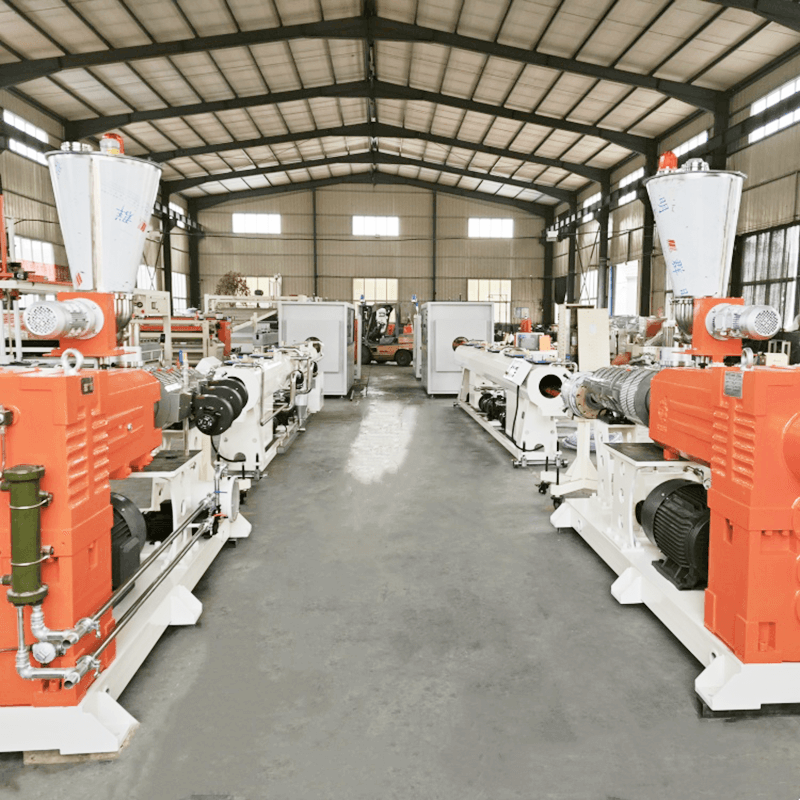
Core Components of a Modern PVC Pipe Production Line
Material Mixing and Gravimetric Feeding Systems
High-speed heating and cooling mixers prepare the dry blend before extrusion begins. Operators load PVC resin, thermal stabilizers, internal and external lubricants, and calcium carbonate into the mixing vessel. The hot mixer elevates the batch temperature to approximately 120°C. Friction between the high-speed impeller blades and the PVC compound generates the necessary heat. This mechanical friction drives off trapped moisture and ensures uniform dispersion of additives like titanium dioxide.
The cold mixer then rapidly drops the compound temperature below 40°C using a water-jacketed cooling system. This rapid cooling prevents premature plasticization and stops the material from agglomerating in the storage silos. If you skip the cooling phase, the hot compound will bridge in the hopper and starve the extruder.
Gravimetric dosing units control the exact mass of these materials entering the extruder throat. Volumetric feeders often fail due to bulk density variations in the dry blend. Gravimetric systems weigh the material continuously using load cells. They adjust the feed screw speed automatically to maintain a constant mass flow rate. Precise control over the resin mixture prevents material degradation inside the barrel. Consistent blends ensure the final pipe withstands field joining stresses. Brittleness from poor mixing causes the pipe ends to crack during the downstream belling process.
- Load raw PVC resin and minor additives into the hot mixer.
- Run the impeller at high speed until the friction heats the batch to 120°C.
- Discharge the hot blend into the water-jacketed cold mixer.
- Cool the mixture to 40°C to stabilize the compound.
- Transfer the stabilized dry blend to the gravimetric dosing silo.
Conical vs. Parallel Twin-Screw Extruders
Extruder selection forms the heart of your operation. Conical twin-screw extruders handle high-pressure, lower-speed tasks exceptionally well. They provide excellent shear and plasticization at lower RPMs. They fit standard PVC pipe manufacturing equipment perfectly. The conical design naturally compresses the melt as it moves forward toward the die head, generating high pressure without requiring excessive screw length.
Parallel twin-screw models suit high-throughput, large-diameter pipe production. They offer longer plasticization times due to their extended Length-to-Diameter (L/D) ratios. This extended melting zone prevents thermal degradation at high output rates. When pushing 1000 kg/hr of material, a parallel screw prevents the PVC from burning before it reaches the die.
Motor and drive systems require careful evaluation on the factory floor. Standard AC motors consume significant power and lose efficiency at lower speeds. Permanent magnet synchronous motors (PMSM) offer superior energy efficiency. PMSM drives maintain high torque at low speeds, which is exactly what twin-screw extruders require. They reduce electrical consumption across the entire line and run significantly cooler than traditional induction motors.
| Technical Feature | Conical Twin-Screw Extruder | Parallel Twin-Screw Extruder |
| Shear Rate Profile | High shear at lower rotational speeds | Lower, more uniform shear across the barrel |
| Plasticization Zone | Rapid melting zone due to decreasing volume | Gradual, extended melting zone |
| Best Application | Standard UPVC pipes, high calcium filler ratios | Large diameter, high-throughput pressure pipes |
| Melt Pressure | Naturally high due to conical geometry | Requires specific screw design to build pressure |
Die Heads and Vacuum Calibration Tanks
The die head shapes the molten PVC into a tubular profile. Spider-type and spiral die heads distribute the melt evenly around a central mandrel. Spider legs hold the mandrel in place, but they split the melt flow. This splitting creates weld lines in the extruded pipe. Advanced die designs minimize these flow marks by increasing the compression ratio after the spider legs. High compression forces the split melt to fuse back together completely. This eliminates weak points where pipes might split during field installation or pressure testing.
Vacuum sizing tanks cool the pipe efficiently while maintaining its exact shape. The hot, pliable pipe enters a brass or stainless steel sizing sleeve under negative pressure. The vacuum pulls the hot plastic outward against the calibrator wall. This maintains strict outer diameter (OD) tolerances. Closed-loop systems recirculate water continuously through the tank. Spray nozzles cool the pipe evenly across its entire circumference.
Uneven cooling causes warping, bowing, and ovality. Oval pipes fail to seal properly when joined with elastomeric gaskets in the trench. You must monitor the water temperature and spray nozzle alignment constantly. A clogged nozzle creates a hot streak on the pipe, leading to immediate dimensional failure.
![Modern PVC pipe production line and extrusion equipment setup]()
Downstream Integration: Manufacturing Pipes for Secure Joining
Inline Belling and Socketing Machines
How do you connect or join PVC pipe in the field? Plumbers and contractors do not extrude pipe on-site. They rely on the manufacturer to provide ready-to-join ends. The production line must prepare the pipe ends accordingly. Automated belling machines integrate directly into the extrusion line, sitting just after the cutting saw.
These machines heat the cut pipe end using infrared or ceramic ovens. Infrared heaters rotate around the pipe end to apply heat evenly. Uneven heating causes the socket to warp or tear during the forming process. Once the plastic reaches its softening point, a mechanical mandrel drives into the heated pipe. These machines form U-type, R-type, and rectangular sockets automatically. The pipe cools over the mandrel, locking in the precise internal dimensions required for a watertight joint.
Solvent Cement Socket vs. Elastomeric Ring (Gasket) Preparation
Solvent welding requires incredibly smooth, straight sockets. The equipment must create precise interference fits. The inner diameter of the socket must taper slightly from the mouth to the root. This taper forces the solvent cement into the microscopic pores of the plastic as the installer pushes the pipes together. The belling machine uses external air pressure to form the softened pipe against a highly polished steel mandrel.
Gasket joints need entirely different tooling and preparation. The belling process forms Rieber or standard elastomeric ring grooves. A collapsible mandrel expands inside the heated pipe end. It creates the precise groove geometry required to hold the rubber seal. The plastic cools and shrinks around the mandrel before the mechanical segments collapse and retract. This ensures leak-proof field performance under high municipal water pressure.
| Joint Type | Tooling Requirement | Socket Geometry | Primary Field Application |
| Solvent Cement | Solid, polished steel mandrel | Slight internal taper for interference fit | Plumbing, conduit, low-pressure irrigation |
| Elastomeric Gasket | Collapsible mechanical mandrel | Deep internal groove for rubber ring | Municipal water mains, sewer lines |
| Threaded | Inline threading lathe | NPT or BSPT cut threads | Industrial chemical processing lines |
Cutting, Chamfering, and Threading Equipment
Planetary cutters handle large diameters efficiently. They rotate around the pipe, cutting through the wall without deforming the circular shape. They utilize carbide-tipped blades to cut cleanly through heavy-wall pressure pipes. Integrated vacuum systems extract the plastic swarf instantly. Dust accumulation ruins the belling machine sensors and creates a massive housekeeping hazard. Guillotine or saw cutters work best for a smaller PVC conduit production line, where the wall thickness is minimal and line speeds are high.
Inline chamfering tools bevel the pipe edges during the cutting cycle. A sharp 15-degree bevel prevents gasket displacement during field installation. If a pipe lacks a proper chamfer, the blunt edge will catch the rubber ring and push it out of its groove as the pipes slide together. This causes immediate joint failure during pressure testing. Threading equipment can also be integrated for specific industrial piping applications, requiring thick walls and precise pitch control.
Ensuring Dimensional Compatibility for Field Connections
Extrusion parameters directly affect standard compliance. ASTM and ISO standards dictate strict OD and wall thickness ranges. Precise dimensions guarantee reliable field-applied solvent cements and mechanical fittings. Inline measuring devices monitor these dimensions continuously. They reject out-of-spec pipes before they reach the belling machine. This prevents defective products from reaching the end-user and causing catastrophic leaks inside a building.
Evaluating PVC Pipe Manufacturing Equipment for Scalability
Throughput Capacity and Line Speed
Define success criteria based on kg/hr output versus required pipe dimensions. SDR (Standard Dimension Ratio) and Schedule ratings dictate wall thickness. Thicker walls require slower line speeds to ensure complete cooling in the vacuum tanks. You must balance maximum line speed against available cooling capacity.
Pushing a line too fast results in internal heat retention. The pipe might feel cool on the outside, but the core remains soft. The pipe will deform when stacked on pallets or when the belling machine clamps onto it. Calculate the Overall Equipment Effectiveness (OEE) to measure true line productivity, factoring in scrap rates and changeover downtime.
Energy Consumption and Resource Efficiency
Evaluate the specific energy consumption (kWh/kg) of the entire Plastic Pipe Production Line. High-efficiency ceramic heaters and insulated barrels reduce heat loss to the factory floor. Closed-loop water cooling systems minimize environmental impact. They filter and chill the process water for continuous reuse.
This dramatically lowers utility consumption compared to open-loop systems that dump heated water down the drain. Variable frequency drives (VFDs) on vacuum pumps and water pumps further reduce electrical draw during operation. A VFD slows the pump down when full vacuum pressure isn't required, saving massive amounts of electricity over a 24-hour shift.
Automation, PLC Controls, and Quality Monitoring
Centralized PLC systems synchronize the entire line. Siemens, B&R, and Omron offer robust control platforms that link the extruder, haul-off, and cutter. The haul-off speed must match the extruder output perfectly. If the haul-off pulls too fast, the pipe wall thins out. If it pulls too slow, the pipe jams in the die. Modern Human-Machine Interfaces (HMIs) store recipe data for different pipe sizes. This speeds up changeover times significantly.
Inline ultrasonic wall thickness measuring devices provide real-time quality control. Ultrasonic sensors measure wall thickness at four or eight points around the circumference. The HMI displays a real-time radar chart. Operators spot eccentricities immediately. The PLC adjusts the haul-off speed or die centering automatically. This saves substantial raw material over a production shift by running the pipe at the absolute minimum allowable wall thickness.
Implementation Risks and Mitigation in Plastic Pipe Production
Managing Material Degradation and Burn-on
PVC remains highly heat-sensitive. It degrades rapidly if exposed to excessive temperatures, releasing corrosive hydrochloric acid gas. Improper screw geometry causes localized shear heating. This leads to degradation and black spots in the final product. Heater band failures create similar thermal inconsistencies. Melt fracture occurs when the extrusion speed exceeds the material's relaxation time. The pipe surface becomes rough and loses its gloss.
Specify extruders featuring internal screw core temperature control. Oil or water circulates through the screw shaft to regulate heat from the inside out. Use highly responsive solid-state relays (SSRs) for heater bands. SSRs pulse rapidly to maintain exact temperature setpoints without overshooting. Adjusting the die temperature and lowering the haul-off speed resolves most surface defects.
Calibration Challenges and Wall Thickness Variations
Inconsistent vacuum pressure causes out-of-spec pipes. The pipe pulls away from the sizing sleeve, altering the outer diameter. Haul-off speed fluctuations stretch the hot plastic unevenly. This ruins dimensional stability. You cannot securely join these defective pipes in the field. Solvent cement will not bridge large gaps between an undersized pipe and a standard fitting.
Implement servo-driven haul-off caterpillars. Servo motors provide exact speed control without surging. Install automated vacuum regulating valves on the calibration tanks. They maintain constant negative pressure regardless of water flow fluctuations. Ensure the haul-off belts apply even pressure without crushing the pipe. Worn rubber pads on the caterpillar tracks cause slippage, which immediately translates to wall thickness variations.
Floor Space, Installation, and Operator Training
Underestimating the linear footprint creates massive installation headaches. Cooling tanks for thick-walled pipes stretch for dozens of meters. Downstream belling equipment requires significant lateral space for the pipe ejection racks. Extrusion lines cannot bend around corners; they require a perfectly straight run.
Conduct 3D facility layout planning prior to procurement. Map out utility drops for water, compressed air, and heavy three-phase power. Mandate vendor-supplied on-site commissioning. Train operators thoroughly on startup and shutdown procedures. Improper shutdown leaves stagnant PVC in the barrel, causing severe degradation. Operators must purge the barrel completely with a specialized purging compound before turning off the heaters.
Strategic Procurement Considerations
Vendor Support and Spare Parts Logistics
Analyze the availability of critical wear components. Screws, barrels, and die inserts wear out from abrasive calcium carbonate fillers. Fast replacement minimizes costly downtime. Choose vendors maintaining local spare parts inventories. Verify their technical support response times. Request documentation on routine maintenance schedules. Predictable wear patterns allow for proactive parts ordering before a catastrophic failure halts production.
Interoperability of Production Modules
Assess the modularity of your PVC pipe extrusion systems. Modular lines facilitate future upgrades seamlessly. You might add co-extrusion layers later. This allows the use of recycled core materials with virgin outer skins, reducing material costs while maintaining a perfect surface finish. Distinct color striping requires auxiliary extruders mounted on top of the main die. Ensure the main control panel can integrate these additional modules easily. Open-architecture PLC software prevents vendor lock-in for future expansions.
Conclusion
A profitable extrusion system balances raw output with precise downstream processing. Pipes must meet strict joining and installation standards. Prioritize equipment manufacturers based on local spare parts availability. Evaluate the energy efficiency of their drive systems carefully. Check the modularity of their belling and socketing units to ensure future flexibility.
- Request detailed line layout drawings from shortlisted vendors to verify facility fit and utility routing.
- Schedule material trials using your specific PVC formulation to validate throughput claims and surface finish quality.
- Verify the dimensional tolerances of socketed ends during vendor test runs using standard go/no-go gauges.
- Establish a preventative maintenance schedule for extruder screws and vacuum calibration sleeves before taking delivery.
FAQ
Q: What is the average footprint of a PVC conduit production line?
A: A standard conduit line requires approximately 15 to 25 meters of linear floor space. This includes the extruder, die head, vacuum calibration tank, haul-off unit, cutter, and a simple tipping table. Larger diameter lines require significantly longer cooling tanks and automated belling machines, extending the footprint up to 40 meters.
Q: How does a belling machine prepare PVC pipe for joining?
A: The belling machine heats the cut end of the pipe until the plastic softens. A mechanical mandrel then inserts into the heated end, expanding it to form a specific socket shape. This socket accommodates either solvent cement or an elastomeric rubber gasket for field installation.
Q: What is the difference between UPVC and CPVC pipe extrusion systems?
A: CPVC possesses a higher melt viscosity and is more heat-sensitive than UPVC. CPVC extrusion systems require specialized screw designs with lower shear rates. They also need heavily chrome-plated or specially treated die heads to prevent corrosive wear from the higher chlorine content.
Q: How much water does a vacuum calibration tank consume?
A: Modern vacuum calibration tanks utilize closed-loop recirculation systems. They consume very little fresh water during normal operation. The primary water loss occurs through minor evaporation and pipe carryover. You only need to top up the system periodically, making it highly resource-efficient.
Q: Can one production line manufacture multiple pipe diameters?
A: Yes, a single extrusion line can produce a range of pipe diameters. You must change the extrusion die head, the vacuum sizing sleeve, and the rubber seals on the calibration tank. You also need to adjust the haul-off caterpillar positions and change the belling machine mandrels.
Q: What causes wall thickness variations during PVC pipe extrusion?
A: Wall thickness variations stem from several factors. Inconsistent raw material feeding, surging inside the extruder barrel, or fluctuating haul-off speeds cause longitudinal variations. Poorly centered die heads or uneven cooling in the vacuum tank cause circumferential variations.



 +86-18561886575 (Mr.Wu)

 +8618561886575
 238 Yangzhou West Road, Jiaozhou City, Qingdao City, Shandong Province