Zhongrui's High-capacity PP Packaging Belt Production Line is engineered for efficiency and high output. This innovative machine produces durable, flexible, and cost-effective PP straps, replacing traditional steel straps across various industries. Ideal for manufacturers seeking quality and sustainability.
According to many years of plastic machinery development and design experience, in the introduction of foreign advanced technology and digestion and absorption, on the basis of self-developed PE pipe production line. Has the unique structure, the design is novel, the equipment entire line layout is reasonable, the control performance is strong and so on.
The PE/PPR Pipe Production Line delivers reliable and efficient manufacturing of various pipes for water supply and drainage in agriculture and construction. Experience advanced technology and precision for high-quality production.
Discover the Highly Cost Effective PVC Pipe Production Line from Zhongrui. Engineered for durability and efficiency, this advanced production line ensures high-quality PVC pipes suitable for a variety of applications. Experience seamless operation, reduced maintenance, and significant cost savings.
The Composite Infiltration Irrigation Pipe Production Line is a high-efficiency system designed to produce drip irrigation tape for agricultural applications. With precision control, energy-saving technology, and advanced automation, it ensures superior performance in greenhouse, field crop, and water conservation irrigation systems.
Discover the PVC Hose Production Line designed for efficient, high-speed manufacturing of PVC hoses. Our advanced system ensures precision, versatility, and durability, making it an ideal choice for various industrial applications.
The PVC Imitation Marble Sheet Slab Extruder Machine Production Line is designed for producing high-quality, durable, and visually appealing marble-like PVC sheets. Offering fire resistance, water resistance, and high-temperature durability, it’s ideal for a variety of interior decoration applications. This advanced extrusion line guarantees high efficiency and stable output, making it a top choice for businesses looking to scale up production.
Zhongrui's PMMA Board Production Line is designed for precision, high-output plastic sheet manufacturing. With advanced technology including a vertical three-roll calender, Siemens motor, and ABB inverter, it ensures high plasticizing ability and energy-efficient performance. Ideal for producing PMMA, PC, and ABS sheets for construction, packaging, and automotive industries.
0
0
Plastic Pipe Extrusion Line Components Buyers Should Know
Views: 0 Author: Site Editor Publish Time: 2026-07-15 Origin: Site
Capital expenditure on extrusion machinery carries high operational stakes. Selecting the wrong equipment configuration directly impacts yield, increases material waste, and lowers overall profitability. Buyers often evaluate machinery based on top-line output capacity while overlooking the specific tolerances, material compatibility, and integration capabilities of individual line components. This misalignment leads to frequent downtime, inconsistent pipe wall thickness, and premature equipment wear. Mitigating these risks requires a granular evaluation of the entire integrated manufacturing system. This guide breaks down the critical components of a plastic pipe extrusion line, providing a technical framework to evaluate vendor specifications against actual production requirements.
Key Takeaways
Capacity Planning Dictates System Sizing: Accurately calculating required throughput (kg/hr) is the foundational step; overestimating leads to wasted capital, while underestimating causes downstream cooling bottlenecks.
Screw and Barrel Geometry Dictate Output Quality: Matching the L/D (Length to Diameter) ratio and screw design to the specific polymer (e.g., PVC vs. HDPE or PP-R) is non-negotiable for optimal melt homogeneity and shear friction.
Downstream Precision Controls Yield: Vacuum calibration and cooling tank configurations are the primary factors in maintaining dimensional stability and preventing pipe collapse.
Specialized Applications Require Dedicated Tooling: Standard lines cannot be easily retrofitted for complex geometries; investments in a plastic corrugated pipe extrusion line or an irrigation pipe extrusion line require specialized corrugators or inline dripper insertion units.
Automation Drives Operational Efficiency: Gravimetric dosing, synchronized PLC controls, and integrated auxiliary equipment reduce raw material waste and lower the long-term cost per meter of pipe produced.
System Architecture: Anatomy of a Plastic Pipe Extrusion Line
Treating an extrusion line as a single machine leads to bottlenecks and severe integration failures. You must view it as a synchronized system of independent components. Each section must communicate seamlessly with the others. Capacity and throughput alignment dictates the success of the entire operation. You must evaluate the required kg/hr output accurately to properly size the main extruder motor. This ensures the motor aligns perfectly with downstream cooling capacities. Mismatched capacities cause material degradation or cooling failures. If the extruder pushes more plastic than the tanks can cool, the pipe will deform before it reaches the saw.
The mechanical foundation of the system relies heavily on the gearbox and thrust bearing assembly. The gearbox transfers power from the drive motor to the screw. It must handle massive torque loads during startup and continuous operation. The thrust bearing absorbs the backward pressure generated by the screw pushing molten polymer forward through the die. If you undersize the thrust bearing, the screw will eventually push back into the gearbox, destroying the internal gears and causing catastrophic line failure.
We categorize the system into four primary operational zones. You must assess the integration capabilities of these zones, focusing heavily on communication protocols. The main extruder must talk to all auxiliary equipment continuously. Closed-loop feedback prevents material surges, stabilizes the entire production run, and minimizes scrap generation.
Auxiliary Pre-feeding Zone: Handles material storage, drying, blending, and conveying to the extruder hopper.
Upstream Zone: Consists of the motor, gearbox, barrel, and screw. This zone melts, mixes, and pumps the polymer.
Tooling Zone: Includes the die head and adapter. This section shapes the molten polymer into the desired pipe profile.
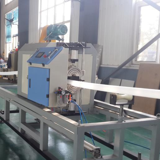
Downstream Zone: Comprises the vacuum calibration tanks, cooling baths, haul-off units, and cutting saws. This area freezes the dimensions and cuts the product to length.
System Capacity Alignment Parameters
Target Pipe Diameter (mm)
Typical Extruder Size (mm)
Estimated Output (kg/hr)
Minimum Cooling Length (m)
16 - 63
45 - 65
150 - 300
12 - 18
75 - 250
75 - 90
350 - 600
24 - 36
315 - 630
120 - 150
700 - 1200
40 - 60
800 - 1200
150 - 200
1200 - 2000
60+
Primary Extruder Components: Evaluating Melt and Feed Mechanisms
Auxiliary Material Handling and Feed Throat
If you run hygroscopic materials like nylon or certain polycarbonates without proper drying, you will get moisture bubbles in the melt. Hygroscopic materials absorb moisture directly from the ambient air. You need dehumidifying dryers and automated vacuum conveying systems. Moisture causes severe structural flaws in the final pipe. It creates voids in the pipe wall and weakens the polymer chains. Proper drying ensures the resin enters the extruder at the correct dew point, typically around -40°C for sensitive engineering resins.
Feed throat engineering requires careful evaluation during procurement. You must assess the feed throat cooling jacket efficiency. Proper cooling is mandatory at this specific junction. It prevents premature resin melting before the pellets enter the screw flights. Early melting causes bridging. The plastic sticks to the walls of the feed throat and blocks material flow into the barrel entirely. A blocked feed throat starves the screw and halts production immediately. Water-cooled jackets maintain the optimal temperature gradient. However, if the water is too cold, condensation forms inside the throat, causing resin dust to clump and restrict flow. Operators usually target a feed throat temperature between 40°C and 50°C.
Hopper and Gravimetric Feeding Systems
Standard volumetric feeders measure material strictly by volume. They ignore natural changes in bulk density. If you switch from virgin pellets to a regrind mix, the bulk density changes, and a volumetric feeder will feed a different mass of plastic per minute. Gravimetric dosing systems measure material accurately by weight using load cells. Gravimetric control ensures precise material-to-meter weight ratios. It reduces resin costs significantly over long runs and maintains uniform cross-sections throughout the entire production cycle. This precision eliminates the need to over-extrude to meet minimum wall thickness standards.
Implementation risks exist with any automated feeding system. Bridging or rat-holing often occurs inside the hopper. This happens frequently with poorly flowing regrind materials or light powders. You can mitigate this risk easily during the design phase by installing mechanical agitators inside the hopper body. These rotating arms keep the material flowing consistently into the feed throat. Consistent feeding prevents pressure fluctuations inside the extruder barrel, which directly translates to stable pipe dimensions.
Barrel and Screw Design Specifications
Understanding melting mechanics is vital for equipment selection. Mechanical shear generates the majority of the melting heat. The turning screw creates intense friction against the barrel wall, shearing the polymer pellets until they melt. You must evaluate screw design carefully. Look for the optimal shear-to-heat ratio for your specific resin. This reduces reliance on external barrel heater bands and prevents thermal degradation of the sensitive polymer chains.
A standard single screw features three distinct zones. The feed zone conveys solid pellets forward from the hopper. The compression zone features a decreasing flight depth. This compresses the polymer, forces out trapped air, and melts the plastic via shear friction. The metering zone pumps the uniform melt at a consistent pressure to the die head. The Length to Diameter (L/D) ratio dictates the residence time of the plastic inside the barrel. Basic profiles might use a 24:1 L/D ratio. High-output polyolefin lines often require 30:1 or 36:1 L/D ratios to ensure complete melting at high RPMs.
Technical evaluation involves choosing between specific extruder types. You will choose either a single-screw or twin-screw configuration. Twin-screw extruders come in conical and parallel designs. PVC requires twin-screw setups. It needs low-shear processing to prevent burning. Polyolefins like HDPE and PP behave differently. They utilize single-screw extruders. These screws feature specific barrier flights for optimal melting and mixing.
Extruder Configuration and Polymer Compatibility
Extruder Type
Primary Polymer Compatibility
Shear Characteristics
Typical Pipe Applications
Single-Screw Extruder
HDPE, LDPE, PP, PPR
High shear, relies on barrier flights for mixing
Water supply, gas distribution, industrial piping
Conical Twin-Screw Extruder
PVC (Dry blend powder)
Low shear, high compression ratio
Sewer pipes, drainage, electrical conduits
Parallel Twin-Screw Extruder
PVC, highly filled compounds
Low shear, excellent distributive mixing
Large diameter pressure pipes, high-output lines
Wear resistance dictates the long-term equipment lifespan. Evaluate bimetallic barrels for extended longevity. Look for tungsten-carbide coated screws when processing highly filled materials like calcium carbonate-loaded PVC. Abrasive additives wear down standard steel very quickly. Upgraded metallurgy maintains tight tolerances between the screw flights and the barrel wall over years of operation. It preserves your initial investment and prevents output drops caused by melt slipping backward over worn flights.
Breaker Plate, Screen Changer, and Feed Pipe Adapter
The breaker plate sits at the end of the barrel. It converts the rotational flow of the polymer melt into a linear flow before it hits the die. It also supports the filtration screen pack. This screen removes unmelted particles, foreign contaminants, and degraded polymer bits. Clean melt ensures high pipe burst strength. It prevents stress concentrators from forming in the pipe wall, which would otherwise cause the pipe to fail under pressure testing.
Scalability depends heavily on your screen changer choice. Manual changers require complete line stoppages. You have to shut down the extruder, unbolt the housing, swap the screen, and restart. Continuous hydraulic screen changers operate much differently. They use hydraulic accumulators to push a new screen into the melt stream in a fraction of a second. They prevent line stoppages during filter changes. This is critical for high-capacity continuous operations. It eliminates scrap generated during startup and shutdown sequences and keeps the thermal profile of the extruder perfectly stable.
Assess the feed pipe adapter design carefully. This is the transition zone connecting the barrel to the die head. The adapter must feature highly streamlined internal flow channels. Smooth channels prevent material hang-up. Stagnant material causes thermal degradation, resulting in black spots or streaks in the final pipe. The adapter must also maintain the melt temperature precisely using dedicated heater bands and thermocouples.
Die Head and Tooling: Engineering Dimensional Accuracy
Die Head Configurations
Die heads shape the molten polymer into a continuous pipe profile. Spider dies are common for PVC processing. They use internal metal legs to hold the central torpedo or mandrel in place. The polymer melt must flow around these legs, splitting and then rejoining before exiting the die. This rejoining creates weld lines along the length of the pipe. While acceptable for low-pressure PVC applications, these weld lines are weak points.
Spiral mandrel dies are preferred for polyolefins like HDPE. Spiral designs eliminate structural weld lines entirely. The melt enters the die and is distributed through a series of overlapping spiral channels cut into the mandrel. As the melt moves forward, the channels become shallower, forcing the plastic to flow over the lands and merge into a homogeneous tube. This design handles high melt pressures efficiently and distributes the melt evenly around the entire circumference, ensuring uniform wall thickness.
Evaluate co-extrusion die heads for specialized applications. Multi-layer pipes require highly complex tooling. PP-R plumbing pipes often need fiberglass-reinforced middle layers to reduce thermal expansion. Co-extrusion dies merge different melt streams from multiple extruders seamlessly just before the die exit. Assess the internal flow channel design carefully. You want to minimize melt pressure drop. This prevents material degradation and eliminates burn spots on the inner wall.
Application-Specific Tooling: Irrigation Pipe Extrusion Line
Standard tooling cannot produce specialized agricultural pipes. You must evaluate specific integration requirements. An irrigation pipe extrusion line requires inline dripper feeding. It needs precise spacing and punching mechanisms. The die head must accommodate the insertion of these plastic emitters without disrupting the melt flow. The emitters are fed via a high-speed centrifugal bowl feeder and shot through the center of the die head directly into the hot pipe as it forms.
Success criteria depend on high-speed mechanical synchronization. The dripper insertion unit must match the main haul-off speed exactly. This ensures exact dripper spacing, whether the farmer requires 20cm or 50cm intervals. It prevents micro-leaks around the insertion points by ensuring the hot polymer bonds perfectly to the emitter body. The punching mechanism must operate cleanly at high line speeds, often exceeding 100 meters per minute. It must remove the plastic slug covering the emitter hole without leaving debris inside the pipe, which would clog the irrigation system in the field.
Downstream Equipment: Sizing, Cooling, and Haul-Off
Vacuum Calibration Tanks
Extruded plastic exits the die in a molten state. It lacks structural integrity at this critical stage. Without precise immediate sizing, the pipe will warp or collapse under its own weight. Vacuum calibration tanks freeze the outer dimensions instantly. They pull the molten plastic against a rigid sizing sleeve using negative atmospheric pressure.
Review the technical specifications of the sizing sleeves. Beryllium copper sleeves offer excellent heat transfer properties, pulling heat out of the plastic rapidly, but they wear out faster under abrasive conditions. Stainless steel sleeves provide superior wear resistance but cool the pipe slightly slower. Water ring designs at the entrance of the sleeve ensure uniform initial cooling and provide a lubricating layer of water between the hot plastic and the metal sleeve.
Dual-chamber vacuum tanks are essential for high-speed lines. They maintain vacuum stability in the first short chamber, locking in the pipe dimensions. You can adjust cooling water flow and vacuum levels independently in the second, longer chamber without losing suction at the die exit. This prevents the pipe from chattering or pulsating as it enters the tank.
Cooling Baths and Spray Tanks
Cooling methods vary based on specific pipe dimensions. Immersion cooling submerges the pipe entirely in a bath of chilled water. This works well for small diameter pipes. Spray cooling uses high-pressure nozzles to target the pipe from all angles. Spray cooling provides better heat transfer efficiency for thick-walled pipes. It aggressively breaks the insulating steam layer that forms naturally around the hot pipe surface. Breaking this vapor barrier accelerates the cooling process and prevents the core of the pipe wall from retaining heat.
Capacity planning requires accurate thermodynamic calculations. You must calculate the required cooling tank length based on the polymer's thermal conductivity. Amorphous polymers cool differently than semi-crystalline polymers. Semi-crystalline polymers like HDPE shrink significantly and release latent heat of crystallization as they solidify. This requires much longer cooling tanks. Insufficient cooling length causes the pipe to deform in the haul-off unit. The tracks will crush the soft pipe, leading to ovality issues and rejected batches.
Variables Impacting Cooling Tank Length
Variable
Impact on Cooling Requirements
Operational Adjustment
Line Speed (m/min)
Higher speeds reduce residence time in the tank.
Add secondary spray cooling tanks to the line.
Wall Thickness (mm)
Thicker walls retain core heat longer due to poor polymer conductivity.
Lower chilled water temperature; increase spray pressure.
Polymer Type
HDPE releases latent heat; PVC cools faster.
Design tank length specifically for the worst-case resin.
Water Temperature
Warmer water drastically reduces heat transfer rates.
Install dedicated industrial chillers and heat exchangers.
Haul-Off (Puller) and Cutting Units
Traction and synchronization control the final pipe dimensions. Caterpillar haul-offs grip the pipe securely and pull it through the cooling tanks at a constant velocity. They use 2-belt to 8-belt configurations. The number of belts depends on the pipe diameter. A 16mm pipe needs a 2-belt puller, while a 1200mm pipe requires an 8-belt or 10-belt puller to distribute the gripping force and prevent crushing.
Servo-motor drives are an absolute necessity for the haul-off. They provide zero-slip, constant-tension pulling. If the haul-off surges or slips, the pipe wall thickness varies in a wave pattern, failing quality control checks. The pneumatic pressure applied to the upper belts must be adjustable to accommodate different pipe stiffness levels.
Cutting technologies must match the specific application. Planetary saws are standard for large diameters. The saw blade rotates around the circumference of the pipe, cutting through the wall and chamfering the edges simultaneously. This prepares the pipe for immediate socketing or jointing. Swarfless cutters work best for smaller pipes. Guillotine or rotary cutters slice through the plastic without generating chips or dust. They remove the need for secondary finishing operations and keep the production environment clean and safe.
Specialized Configurations: Corrugated Pipe Production
Plastic Corrugated Pipe Extrusion Line Components
Corrugated pipes require completely different downstream equipment. The corrugator unit replaces standard vacuum tanks. This is the core difference in a plastic corrugated pipe extrusion line. The corrugator uses a continuous track of moving mold blocks to form the ribs. The molten plastic tube is extruded directly into the moving blocks. It is pressed against the corrugated profile using internal air pressure or external vacuum drawn through tiny slits in the mold blocks.
Assess the mold block cooling efficiency carefully. Compare water-cooled systems against air-cooled systems. Water cooling extracts heat much faster by circulating chilled water directly through channels inside each moving block. This directly impacts your maximum line speed. It also determines the profile definition of the corrugations. Superior cooling freezes the plastic instantly, preventing the ribs from sagging or deforming before they solidify.
PP Corrugated Pipe Production Line Specifics
Polypropylene behaves differently than PE or PVC. It has specific shrinkage rates and requires distinct cooling profiles. You must manage the higher melt temperatures of PP carefully. The equipment must handle these thermal demands without warping the mold blocks or causing the shuttle system to bind due to thermal expansion.
Implementation risks are higher with polypropylene. Ensure the corrugator vacuum system is robust. A PP corrugated pipe production line must accurately form stiff rib profiles to meet high ring stiffness classes (e.g., SN8 or SN16). Weak vacuum leads to webbing between the ribs. It causes unacceptable thinning at the crests of the corrugations. This compromises the structural integrity of the final product, causing it to fail under soil load testing.
Automation and Quality Control
PLC Control Systems and Line Synchronization
Control systems dictate operational reliability. Centralized HMI panels offer single-point operation, allowing the operator to monitor extruder RPM, melt pressure, barrel temperatures, and haul-off speed from one screen. Decentralized controls complicate troubleshooting and force operators to run back and forth along the line. The real value lies in closed-loop control systems. They tie the haul-off speed directly to the extruder RPM and the gravimetric feeder output. This maintains consistent pipe weight automatically. It compensates for minor fluctuations in melt pressure or bulk density without human intervention.
Energy efficiency impacts long-term profitability. Evaluate the use of permanent magnet synchronous motors (PMSM) for the main extruder drive. PMSM drives offer superior torque at low speeds and consume significantly less electricity than standard AC induction motors. Insulated barrel heaters reduce radiant heat loss into the factory. They lower your overall kW/kg energy consumption. Efficient motors and insulated barrels also reduce the thermal load on your factory HVAC and cooling systems.
Inline Quality Assurance
Manual quality checks using calipers are too slow for modern extrusion. By the time an operator measures a defect, hundreds of meters of scrap have already been produced. Integrating inline quality assurance mitigates production risks. Install ultrasonic wall thickness measurement systems directly after the first vacuum tank. They scan the pipe continuously in 360 degrees. They provide real-time data to the central PLC, which can automatically adjust the haul-off speed or extruder RPM to bring the pipe back into tolerance.
Use inline flaw detectors to automate quality control. These systems spot pinholes, surface defects, and lumps instantly. They trigger alarms before you produce out-of-spec scrap. Automated sorting mechanisms can eject defective pipe sections automatically after the cutting saw. This ensures only perfect products reach your packaging station.
Troubleshooting Extrusion Defects via Component Adjustments
Defect Observed
Likely Component Cause
Corrective Action
Melt Fracture (Sharkskin)
Die head temperature too low; excessive shear.
Increase die zone temperatures; reduce line speed.
Wall Thickness Variation
Haul-off slipping; extruder surging.
Check puller belt pressure; verify gravimetric feeder flow.
Internal Burn Spots
Material hang-up in the feed pipe adapter.
Clean adapter channels; check for failed thermocouples.
Pipe Ovality
Insufficient cooling tank length; warm water.
Decrease line speed; lower chilled water setpoint.
Conclusion
Execute the following steps to ensure your equipment procurement aligns with your production demands:
Audit your current resin data sheets to determine exact L/D ratio and screw geometry requirements before requesting vendor quotes.
Calculate your facility's available chilled water capacity to ensure it can support the required downstream cooling tanks at maximum line speeds.
Specify continuous hydraulic screen changers in your RFQ to prevent line stoppages and scrap generation during high-volume runs.
Require vendors to provide a documented performance trial using your specific material blend prior to final sign-off and shipment.
FAQ
Q: What is the most critical component in a plastic pipe extrusion line?
A: The extruder screw and barrel dictate melt quality, output rate, and material compatibility. They generate the mechanical shear and friction required to melt the polymer. Proper screw geometry ensures optimal melting without degrading the material, making it the foundation of the entire operation.
Q: How do I choose between a single-screw and twin-screw extruder?
A: Single-screw extruders are standard for processing polyolefins like HDPE and PP. Twin-screw extruders are required for heat-sensitive materials like PVC. The twin-screw design provides low-shear processing to prevent thermal degradation and burning during the extrusion process.
Q: What role does auxiliary equipment play in the extrusion process?
A: Auxiliary equipment ensures raw materials are properly conditioned and fed. Devices like dehumidifying dryers, gravimetric feeders, and vacuum conveyors prevent moisture-induced structural flaws. They are critical for maintaining consistent pipe quality, stabilizing melt pressure, and reducing material waste.
Q: What components are unique to a plastic corrugated pipe extrusion line?
A: A corrugated pipe line replaces standard vacuum calibration tanks with a specialized corrugator unit. This unit uses moving mold blocks on a track to form the ribbed profile. Efficient mold block cooling is essential for maintaining high line speeds and sharp profile definition.
Q: Why is spray cooling preferred over immersion cooling for thick-walled pipes?
A: Spray cooling provides superior heat transfer efficiency. It actively breaks the insulating steam layer that forms around the hot pipe surface. This rapid cooling prevents dimensional warping and ensures the pipe core solidifies properly before reaching the haul-off unit.
Q: How does a gravimetric feeding system improve pipe quality?
A: Gravimetric feeders measure material by weight rather than volume using load cells. This ensures precise material-to-meter dosing. It maintains uniform pipe cross-sections, reduces resin consumption, and eliminates inconsistencies caused by natural variations in bulk density or regrind ratios.
Qingdao Zhongrui Plastic Machinery Co., Ltd. is located in Jiaozhou City, Qingdao City, Shandong Province. It is 30 kilometers away from Qingdao Port and only 20 kilometers away from the airport.



 +86-18561886575 (Mr.Wu)
 +8618561886575
 238 Yangzhou West Road, Jiaozhou City, Qingdao City, Shandong Province