Dimensional inaccuracies in extruded plastics directly lead to assembly failures, compromised structural integrity, and high scrap rates. This reality makes the transition from melt to solid state the most critical phase of extrusion. Uneven heat dissipation causes differential cooling, warping, and shrinkage, particularly in complex geometries with varying wall thicknesses. These defects erode profit margins, cause installation issues in the field, and damage manufacturer credibility. Achieving strict tolerances requires moving beyond basic chilling methods. Upgrading to a modern plastic profile production line with engineered vacuum calibration, optimized cooling flow paths, and strict material batching controls is essential for maintaining geometric consistency and operational efficiency.
- Calibration is the Anchor: Vacuum-cooled stainless steel calibration tooling dictates the final shape, locking in the PVC profile geometry before downstream cooling.
- Differential Cooling Causes Warpage: Thicker sections require engineered flow paths and targeted cooling to equalize residence time and prevent internal stress.
- Design for Manufacturability (DFM) Matters: Achievable tolerances depend heavily on the initial profile design; minimizing extreme wall thickness variations reduces the burden on the cooling system.
- Machinery Configuration Dictates Yield: Balancing line speed with cooling tank length and capacity is the primary determinant of dimensional stability and overall equipment effectiveness (OEE).
- Tooling Customization is Non-Negotiable: Complex outputs, such as those from a PVC sealing strip production line, require highly specific, customizable cooling matrices to prevent profile collapse.
The Mechanics of PVC Profile Deformation During Extrusion
Problem Framing (Success Criteria)
Polymer exits the extrusion die in a highly malleable state. At this exact moment, the melt temperature often exceeds 190°C. The material possesses very little structural integrity and remains extremely susceptible to gravity, draw-down tension from the haul-off unit, and ambient temperature fluctuations on the factory floor. The plastic naturally wants to sag, swell, and distort immediately upon leaving the die lip. You must lock the shape before polymer memory induces uncontrolled shrinkage.
Success in extrusion means freezing the exact geometric dimensions before the material reaches the end of the cooling train. Any delay or inefficiency in this initial phase guarantees geometric failure. If the outer skin does not solidify instantly in the calibrator, the profile will drag against the tooling, causing surface defects and dimensional drift. The goal is to create a rigid outer shell that holds the internal chambers in place while the core slowly cools and stabilizes.
Differential Cooling and Wall Thickness Variations
Thicker profile sections retain heat much longer than thinner walls. This physical reality creates severe processing challenges on the extrusion floor. When a profile features a 3mm outer wall and 1mm internal webs, the thin webs freeze almost instantly upon entering the calibration block. They stop contracting. However, the 3mm outer wall remains molten in the center. As it continues down the line, it cools and shrinks. This uneven contraction rate pulls the internal webs out of alignment, leading directly to bowing, twisting, or sink marks on the visible surfaces.
The physical result is a distorted shape that fails quality control checks. Internal stresses build up between the varying sections, locking tension into the final product. Design for Manufacturability (DFM) addresses this issue early in the engineering phase. Designing profiles with uniform wall thicknesses mitigates differential cooling risks before the melt even reaches the calibration stage. Consistent walls ensure consistent heat dissipation, drastically reducing the burden on the cooling equipment.
Impact of Wall Thickness on Cooling Dynamics | Wall Thickness (mm) | Cooling Behavior | Risk of Differential Shrinkage | Required Tooling Adjustment |
| 1.0 - 1.5 | Rapid freezing, minimal core heat retention. | Low (if uniform across profile). | Standard vacuum slots, moderate water flow. |
| 2.0 - 2.5 | Moderate cooling, skin freezes while core remains soft. | Medium (susceptible to bowing). | Targeted water channels near the specific section. |
| 3.0+ | Slow cooling, high heat retention in the core. | High (severe sink marks and warpage). | Extended dry calibration, high-velocity turbulent water flow. |
The Cost of Dimensional Inaccuracies
Downstream impacts on end-users are severe when geometric tolerances drift. Poor fitting and alignment issues disrupt construction schedules. If a window frame profile bows by even two millimeters over a three-meter length, the sash will bind, and the weather stripping will fail to seal. Compromised load-bearing strength creates safety hazards in structural applications. End-users routinely reject entire shipments over minor tolerance deviations. You cannot afford to ship warped materials.
Long-term performance risks also plague inaccurate extrusions. Locked-in residual stress from uneven cooling remains dormant initially. It often leads to premature thermal expansion failures months after installation. When the sun heats a stressed PVC profile, the material attempts to relieve that internal tension, resulting in sudden cracking or severe warping on the building exterior. Operational costs skyrocket due to high rejection rates, and material waste destroys profitability when you consistently miss geometric tolerances.
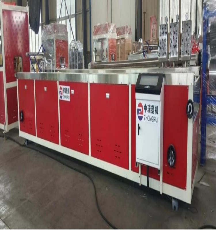
![Vacuum shaping platform for PVC profile cooling]()
Core Cooling Technologies in a PVC Profile Production Line
Solution Categories
Cooling and shape retention happen in specific, engineered stages immediately following the die. The first stage sizes the molten plastic, forcing it into its final dimensions. The second stage removes the bulk of the heat rapidly to prevent the core from remelting the skin. The final stage stabilizes the core temperature, ensuring the plastic is completely solid before the haul-off belts apply crushing pressure. Each stage requires precise mechanical control and aggressive thermal management.
Vacuum Calibration Tooling (The Sizing Stage)
Vacuum-cooled stainless steel components force the hot profile against polished sizing walls. This action dictates the final geometric dimensions. The vacuum pulls the soft polymer outward, while the chilled steel instantly freezes the outer skin. This creates a rigid shell that holds the internal shape intact. The design of these calibration blocks separates average extrusion lines from high-performance operations.
Advanced tooling engineering optimizes this process through internal fluid dynamics. Engineers use reduced channel dimensions near thinner sections to restrict cooling. Conversely, they design longer, wider flow paths near thicker profile sections. This equalizes residence time across the entire shape, maximizing localized heat extraction exactly where it is needed most.
Dry vs. Wet Calibration Methods | Feature | Dry Calibration | Wet Calibration (Vortex/Tank) |
| Cooling Mechanism | Water circulates through internal drilled channels in the steel block. | Water directly contacts the profile within a vacuum-sealed chamber. |
| Surface Finish | Produces a high-gloss, flawless surface finish. | Can leave minor water marks; generally matte finish. |
| Heat Extraction Rate | Moderate to high; limited by the thermal conductivity of the steel. | Extremely high; direct water contact removes heat rapidly. |
| Best Application | Visible exterior surfaces, complex internal webs, initial sizing. | Secondary cooling stages, thick-walled profiles, high-speed lines. |
Water Cooling Tanks: Spray vs. Immersion Systems
Immersion tanks provide uniform, rapid temperature reduction. They work exceptionally well for simple, solid geometries like pipes or thick rods. The water bath surrounds the material completely, pulling heat from all sides simultaneously. However, immersion creates a significant physical problem: buoyancy. The upward force of the water can easily distort hollow or intricate shapes, pushing the profile out of alignment before it fully solidifies.
Spray cooling tanks solve the buoyancy problem for complex profiles. Atomized water droplets provide superior heat transfer compared to a static water bath. The droplets evaporate on contact with the hot plastic, pulling heat away rapidly through phase change. Spray systems prevent buoyancy distortion entirely because the profile rests on support rollers rather than floating. They allow operators to target specific areas of the profile with adjustable nozzles, directing more water to thick sections and less to thin sections. This targeted approach prevents uneven shrinkage and maintains strict geometric tolerances.
Temperature Control Units (TCUs) and Flow Path Optimization
Multi-zone temperature control is an absolute necessity for high-quality extrusion. You must gradually step down the profile temperature as it moves down the line. Dropping the temperature too fast by hitting 190°C plastic with 10°C water causes severe thermal shock. Thermal shock creates brittle profiles that shatter during the cutting process or fail impact tests in the field. TCUs maintain precise, graduated water temperatures in each tank section.
Flow path optimization ensures consistent water velocity throughout the cooling train. Stagnant water pockets in the cooling tank cause localized hot spots, allowing the plastic to soften and warp. You need turbulent flow to maximize heat transfer efficiency. Proper TCU integration guarantees that the cooling matrix remains stable, protecting the structural integrity of the final product.
- Set the primary dry calibration block to a moderate temperature (e.g., 18°C) to freeze the skin without causing thermal shock.
- Adjust the first spray tank zone to 15°C, utilizing high-velocity nozzles directed at the thickest wall sections.
- Set the secondary spray tank zone to 12°C to extract deep core heat as the profile stabilizes.
- Maintain the final immersion or spray zone at 10°C to ensure complete solidification before the haul-off unit.
- Monitor return water temperatures continuously; a delta of more than 3°C indicates insufficient flow or clogged nozzles.
Evaluating Customizable PVC Profile Machinery for Geometric Accuracy
Evaluation Dimensions (Features-to-Outcomes)
Assessing equipment specifications requires a strict focus on features-to-outcomes. Upgrading a PVC profile production line demands careful analysis of your specific product portfolio. You must match the machinery capabilities to your required geometric tolerances. Do not buy raw extruder capacity that your downstream equipment cannot control. Focus heavily on cooling efficiency, vacuum stability, and tooling precision.
Line Speed vs. Cooling Capacity Trade-offs
Extruder output directly dictates the required length of the cooling train. You cannot increase line speed without proportionally increasing cooling capacity. Pushing material faster means the plastic spends less time in the chilling zones. The core temperature must reach a stable, solid state before the haul-off unit grabs the profile.
Higher speeds require exponentially longer or more efficient cooling paths. If the core remains hot and soft, the haul-off belts will crush the hollow chambers, ruining the geometry instantly. You must establish a strict baseline rule on the factory floor: match your extruder's maximum kilogram-per-hour output to the total heat removal capacity of the tanks. Never compromise cooling length to save floor space. A shorter line running at high speeds will only produce scrap.
Tooling Design for Complex and Co-Extruded Geometries
Specialized lines demand advanced tooling designs that go beyond standard calibration. A PVC sealing strip production line often runs co-extruded materials, where rigid and flexible polymers exit the die simultaneously. These different materials possess different thermal conductivities and require independent cooling rates within the exact same profile.
If you cool the flexible PVC lip too fast, it shrinks rapidly, tears away from the rigid base, or loses its elasticity. If you cool the rigid PVC spine too slowly, it warps and fails to hold the weather seal in place. You need customizable PVC profile machinery to handle these conflicting thermal requirements. Modular cooling tank additions allow for rapid tooling changeovers. Custom matrices with isolated water circuits prevent profile collapse during complex co-extrusion runs.
Automation and Closed-Loop Temperature Monitoring
Inline sensors provide real-time data on water temperatures across every zone of the cooling train. Automated flow valves adjust instantly to maintain programmed setpoints. This closed-loop system ignores ambient factory conditions. Summer heat waves or winter drafts will not affect your cooling tanks because the PLC compensates automatically by modulating chiller flow.
Manual temperature checks by operators are too slow and unreliable. By the time an operator notices a temperature spike on a dial gauge, you have already produced fifty meters of scrap material. Automation guarantees consistent heat dissipation and removes human error from the thermal management equation. A modern PVC profile extrusion line relies heavily on these automated controls to maintain tight tolerances shift after shift.
Implementation Risks and Process Mitigation
Implementation Risks
High-end cooling equipment does not guarantee success automatically. Common operational failures occur frequently on the extrusion floor, even with brand-new machinery. You must identify these risks before they ruin your production run. Mechanical degradation, chemical buildup, and human factors all threaten geometric accuracy daily.
Managing Water Quality and System Maintenance
Hard water scaling destroys cooling efficiency faster than any other variable. Mineral deposits from untreated factory water clog the micro-channels of stainless steel calibration pieces. Biological growth, such as algae in the cooling towers, also restricts water flow through the spray nozzles. This leads directly to uneven heat dissipation, localized hot spots, and warped profiles.
Implementing closed-loop water filtration is mandatory for precision extrusion. Chilling systems must remain free of debris and mineral buildup. Establish strict preventative maintenance schedules for all tooling and water handling equipment. Clean water ensures predictable thermal transfer.
- Install a 50-micron inline filtration system on the main water supply to the calibration tables.
- Dose the cooling tower water with industrial algaecide weekly to prevent biological fouling in the spray nozzles.
- Acid-wash all stainless steel calibration blocks every 30 days to dissolve calcium and magnesium scaling.
- Inspect and clean individual spray nozzles during every tooling changeover to ensure full cone coverage.
- Verify chiller compressor pressures and refrigerant levels quarterly to maintain maximum heat extraction capacity.
Operator Error and Calibration Troubleshooting
Operators frequently make improper adjustments to vacuum pressure during startup. Too much vacuum pressure pulls the soft plastic too hard against the steel, causing severe surface drag marks and chatter. Too little vacuum pressure allows the profile to pull away from the sizing walls, resulting in undersized dimensions. Improper water flow adjustments lead to uneven cooling and bowing.
Standardizing operating procedures solves these issues. Base your SOPs on specific material behavior and profile geometry rather than operator preference. Utilize recipe-driven PLC controls to lock in vacuum and temperature parameters. Do not allow operators to guess vacuum settings based on how the profile looks. Train them to read the physical signs of improper calibration and respond with calculated adjustments.
Extrusion Cooling Troubleshooting Matrix | Defect Observed | Root Cause | Corrective Action |
| Chatter Marks (Horizontal lines) | Vacuum pressure too high in the first calibration block. | Reduce vacuum pressure incrementally until the profile slides smoothly. |
| Profile Bowing (Curving left/right) | Uneven cooling between opposing walls. | Increase water flow to the thicker wall or check for clogged nozzles on the hot side. |
| Sink Marks (Depressions on flat surfaces) | Internal webs cooling slower than the outer skin, pulling the surface inward. | Decrease line speed slightly or increase targeted cooling on the adjacent outer wall. |
| Surface Drag (Scratches/Gouges) | Mineral buildup or debris inside the calibration block. | Stop the line, open the block, and polish the internal surfaces. Check water filtration. |
Material Formulation and Batching Variables
Inaccurate batching in the mixing room alters the melt viscosity of the PVC compound. Changes in polymer additives, specifically external lubricants or calcium carbonate fillers, drastically change the thermal conductivity of the plastic. If the material conducts heat differently than the previous batch, your established cooling matrix fails. The profile will warp even if the machinery runs perfectly according to the PLC.
Implement strict upstream batching controls. Foster close collaboration between tooling engineers and material suppliers. Ensure the cooling matrix matches the specific polymer blend being extruded. If you change the filler ratio to reduce costs, you must adjust the cooling parameters to compensate for the new thermal dynamics. Consistency in formulation guarantees consistency in cooling.
Conclusion
Audit your current scrap rates immediately to identify specific cooling failures, differentiating between warpage and surface defects to pinpoint the root cause on the line.
Request comprehensive tooling design reviews and cooling capacity calculations from machinery manufacturers based strictly on your thickest, most complex profile requirements.
Install closed-loop water filtration and automated temperature control units on all existing lines to eliminate ambient factory conditions as a variable.
Standardize operator startup parameters using recipe-driven PLC controls to prevent manual guessing during the critical calibration phase.
FAQ
Q: How does differential cooling affect a PVC profile?
A: Uneven cooling between thick and thin walls causes internal stress. Thicker sections retain heat longer and shrink more than thin sections. This uneven contraction leads to warping, bowing, and failure to meet dimensional tolerances. Ultimately, this causes severe installation issues in the field.
Q: What is the role of the calibration piece in a PVC profile extrusion line?
A: The calibration piece uses a vacuum to hold the molten plastic against a stainless steel mold. This locks in the exact geometric dimensions. Simultaneously, engineered internal water channels initiate the rapid cooling process, freezing the outer skin of the profile.
Q: Why is spray cooling often preferred over immersion cooling for complex profiles?
A: Spray cooling provides targeted, high-efficiency heat transfer. Atomized water droplets evaporate quickly, pulling heat away without creating buoyancy. Immersion tanks create upward buoyancy forces that can easily distort hollow, intricate, or highly complex profile shapes during the cooling phase.
Q: How long should the cooling tank be on a PVC profile production line?
A: Tank length is dictated by maximum line speed, profile wall thickness, and the thermal conductivity of the compound. Thicker profiles running at higher speeds require significantly longer tanks. The core temperature must stabilize completely before the material reaches the haul-off belts.
Q: Can water quality impact PVC profile geometry?
A: Yes. Mineral buildup from hard water can clog the internal cooling channels of calibration tooling. This restricts water flow, causing uneven heat dissipation. The resulting localized hot spots lead directly to subsequent profile distortion and dimensional failures.
Q: How do you prevent shrinkage in extruded PVC profiles?
A: Prevent shrinkage by optimizing the draw-down ratio and ensuring gradual, uniform cooling. Use multi-zone temperature control to avoid thermal shock. Utilize proper DFM principles to minimize wall thickness variations. Always allow the polymer to fully solidify before it reaches the haul-off unit.



 +86-18561886575 (Mr.Wu)
 +8618561886575
 238 Yangzhou West Road, Jiaozhou City, Qingdao City, Shandong Province