Dimensional variance in extrusion creates compounding financial and operational impacts that extend far beyond the factory floor. Minor geometric flaws in a PVC profile often lead to major downstream losses, including rejected shipments and costly rework. When wall thickness fluctuates or cross-sectional deviations occur, the resulting products fail during assembly. Compromised structural integrity and elevated scrap rates directly erode profitability. Inconsistent profiles cause interlocking mechanisms to jam and structural components to fail under load. Relying on reactive, end-of-line sorting guarantees that defective products have already consumed valuable raw materials, energy, and machine time. Shifting the focus toward proactive, systemic quality control changes this dynamic. Integrating continuous monitoring and automated adjustments directly into the extrusion process prevents defects from forming. This approach stabilizes production, ensures strict adherence to geometric tolerances, and protects your bottom line from the hidden costs of material waste.
- Continuous in-line monitoring (e.g., ultrasonic and laser sensors) reduces scrap by detecting geometric deviations before they exceed customer-specified tolerance limits.
- Die design, tooling health, and vacuum calibration are foundational; secondary quality control systems cannot compensate for inherent tooling flaws or uneven cooling.
- Upgrading a plastic profile production line requires a calculated balance between the upfront costs of automated inspection, long-term material savings, and defect prevention.
- Environmental controls, specifically cooling water temperature and ambient factory conditions, are critical variables in maintaining dimensional stability and preventing profile deformation.
The Cost of Geometric Inaccuracy in PVC Profile Manufacturing
Downstream Assembly and Application Failures
Warped or out-of-tolerance profiles create immediate roadblocks during end-user installation. Window frames require exact dimensions to ensure weather-tight seals and proper hardware operation. Interlocking construction materials demand precise mating surfaces. When a profile deviates from its engineered geometry, installers face assembly failures on the job site. Forcing warped pieces together induces stress fractures, while undersized components compromise the structural rigidity of the final assembly. These failures damage brand reputation and lead to expensive warranty claims.
Aligning production with customer-specified dimensional accuracy is non-negotiable. Strict Service Level Agreements dictate acceptable tolerance bands. Failing to meet these standards results in whole-batch rejections. You cannot rely on manual sorting to catch every flaw. Tight-tolerance applications amplify these operational challenges. Components produced on a PVC sealing strip production line must maintain exact compression characteristics. Even a fraction of a millimeter in dimensional drift renders the sealing strip useless, causing leaks and complete product failure in the field.
Material Waste and Margin Erosion
Calculating the true cost of scrap requires looking beyond the raw material thrown into the grinder. You must account for the energy consumed during extrusion, the labor hours spent managing the line, and the machine downtime required for tooling adjustments. Reworking defective batches consumes production capacity that should be generating revenue. Every hour spent troubleshooting geometric inaccuracy is an hour of lost throughput. This operational inefficiency compounds rapidly over a production quarter.
Overweight profiles represent a silent drain on profitability. Running at the top of the tolerance band to avoid undersized rejects consumes excess resin. This hidden cost destroys profit margins. If a profile is engineered to weigh 500 grams per meter, but runs consistently at 515 grams to compensate for poor process control, you are giving away 3% of your material for free. Tightening process controls and maintaining accurate geometry allows you to run closer to the nominal target, directly reducing resin consumption and maximizing yield.
| Defect Type | Root Cause | Operational Impact | Material Waste Potential |
| Overweight Profile | Running at upper tolerance limit | Silent margin erosion | High (Continuous excess resin usage) |
| Warping / Bowing | Uneven cooling or haul-off tension | Assembly failure, batch rejection | Severe (Total product loss) |
| Sink Marks | Improper cooling of internal webs | Aesthetic rejection, structural weakness | Moderate (Requires immediate rework) |
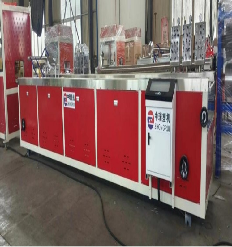
![Vacuum shaping platform for PVC profile extrusion]()
Core Variables Influencing PVC Profile Geometry
Rheology and Melt Temperature
Inconsistent melt viscosity directly causes unpredictable dimensional shifting. Polymer rheology dictates how the material flows through the die. Temperature fluctuations in the extruder barrel alter this viscosity. When the melt temperature spikes, the material flows too freely, leading to die swell as it exits the tooling. This swelling expands the profile beyond its intended dimensions. Conversely, cold spots in the melt create flow restrictions, resulting in undersized sections and internal stress.
Precise thermal regulation in the extruder barrel and die head is mandatory. Heater bands and cooling fans must operate in perfect synchronization to maintain a stable melt temperature across all zones. Thermocouples must be calibrated and placed accurately to read the actual melt temperature, not just the steel temperature of the barrel. Controlling the thermal profile prevents viscosity variations, stabilizes die swell, and provides a consistent foundation for accurate geometry downstream.
Die Design, Flow Balancing, and Tooling Health
Proactive die tuning prevents the uneven material distribution that causes inherent profile deformation. Flow balancing ensures the polymer melt exits the die at a uniform velocity across the entire cross-section. If the flow is unbalanced, faster-moving sections will pull on slower-moving sections, inducing severe warping immediately upon exiting the die. Tooling designers use internal chokes and flow channels to manage this distribution, but operators must fine-tune the die based on real-world running conditions.
Routine tooling inspection identifies wear before it impacts geometry. Flow channels degrade over time due to the abrasive nature of certain additives like calcium carbonate. Carbon buildup restricts flow and causes surface defects. Secondary quality control systems cannot fix a profile that is fundamentally flawed due to degraded or unbalanced tooling.
- Tear down and clean the die assembly immediately after a production run to prevent polymer degradation.
- Inspect die lips for micro-abrasions or physical damage using a magnifying loupe.
- Measure flow channel dimensions with pin gauges to verify they match original tooling specifications.
- Check all internal torpedoes and mandrels for proper alignment and secure fastening.
- Document all wear patterns in a tooling maintenance log to predict future refurbishment needs.
Calibration and Cooling Dynamics
The vacuum calibration table freezes the profile shape immediately after it exits the die. The polymer is still molten and highly malleable at this stage. Vacuum slots pull the outer walls of the profile against the sizing blocks, forcing the material to conform to the precise engineered dimensions. This rapid cooling and shaping process locks in the geometry before the material can sag or deform under its own weight.
Water temperature, flow rate, and vacuum pressure act as the primary stabilizers of profile geometry. Inconsistent cooling water temperature causes uneven shrinkage. If one side of a complex profile cools faster than the other, residual stress builds up, leading to bowing. High flow rates ensure rapid heat transfer, while precise vacuum pressure prevents the walls from collapsing inward. Managing these cooling dynamics prevents post-extrusion shrinkage and ensures long-term dimensional stability.
Haul-off Speed and Tension
Synchronizing extruder output with haul-off speed dictates the final dimensions of the product. The haul-off unit pulls the profile through the calibration table and cooling tanks. If the haul-off runs too fast relative to the extruder output, the profile stretches, reducing wall thickness and narrowing the overall width. If it runs too slow, the material bunches up, causing wavy surfaces and oversized dimensions. This synchronization requires precise drive control and constant monitoring.
Improper tension leads to longitudinal stretching and internal stress. Cleats or belts on the haul-off must grip the profile firmly without crushing it. Excessive clamping force distorts the cross-section, especially on hollow profiles. Uneven pulling induces stress that manifests as warping hours or days after the profile has cooled. Maintaining consistent, gentle tension ensures the profile remains straight and true as it travels down the line.
Common Geometric Defects and Troubleshooting Solutions
Sink Marks and Surface Imperfections
Sink marks occur when thick internal webs cool slower than the outer walls. As the internal mass cools and shrinks, it pulls the outer surface inward, creating localized depressions. Improper cooling is the primary root cause. To mitigate this on the extruder side, operators can adjust the temperature profile to reduce the overall melt temperature, minimizing the volumetric shrinkage during cooling. Lowering the extrusion speed also provides more time for heat transfer in the calibration table.
Adjusting vacuum calibration settings resolves localized depressions. Increasing the vacuum pressure in the specific zone where the sink mark appears pulls the outer wall flush against the sizing block. You must balance this pressure carefully. Too much vacuum increases friction against the calibration blocks, causing chatter marks or line surging. Fine-tuning the water flow directly onto the thick internal webs accelerates their cooling, preventing them from pulling on the outer surface.
Warping, Bowing, and Post-Extrusion Shrinkage
Complex, multi-chamber profiles are highly susceptible to warping. Uneven cooling rates across different sections of the profile induce residual stress. The thicker sections retain heat longer, shrinking more than the thinner sections. This differential shrinkage causes the profile to bow toward the side that cooled last. Residual stress may not manifest immediately; profiles often warp in storage as they acclimate to ambient temperatures.
Troubleshooting requires balancing water flow and haul-off alignment. Direct more cooling water to the thicker sections of the profile to equalize the cooling rate. Check the alignment of the haul-off unit relative to the calibration table. If the haul-off pulls the profile at an angle, it introduces physical stress that results in bowing. Ensure the profile travels in a perfectly straight line from the die to the cutting saw to produce straight, stress-free products.
Essential Quality Control Technologies for a PVC Profile Extrusion Line
In-Line Dimensional Measurement Systems
Continuous, non-contact monitoring provides immediate feedback on geometric accuracy. Laser micrometers measure the outer diameter and overall width of the profile as it moves down the line. These systems scan the profile thousands of times per second, detecting minute deviations in real-time. By catching dimensional drift early, operators can make adjustments before the profile falls out of tolerance, drastically reducing scrap rates.
Ultrasonic gauges provide real-time wall thickness measurement without line disruption. These sensors use sound waves to measure the distance between the inner and outer surfaces of the profile. Integrating ultrasonic sensors into a PVC profile production line allows operators to monitor concentricity and internal web thickness continuously. This data is critical for maintaining structural integrity and preventing the hidden costs associated with overweight profiles.
Off-Line Verification and Metrology
Rigorous cross-sectional checks against original engineering drawings require off-line verification. Optical comparators and shadowgraphs project a magnified image of the profile cross-section onto a screen. Quality control technicians overlay a transparent template of the engineering drawing onto the screen to verify dimensions visually. This method quickly identifies deviations in complex angles and internal geometries that in-line sensors might miss.
Coordinate Measuring Machines verify complex, multi-chamber profiles with extreme precision. A CMM uses a physical probe to measure the exact coordinates of points on the profile surface. This data generates a highly accurate 3D model of the extruded part. Using a CMM ensures absolute compliance with strict customer specifications. While slower than in-line methods, CMM verification provides the definitive proof of geometric accuracy required for critical applications.
Surface and Visual Defect Detection
High-speed machine vision systems identify surface finish inconsistencies automatically. Cameras mounted along the extrusion line capture continuous images of the profile surface. Advanced software analyzes these images to detect sink marks, die lines, scratches, and color variations. These systems operate at line speeds, catching defects that human operators would inevitably miss during visual inspection.
Visual data correlates strongly with internal geometric or tooling issues. A recurring die line indicates a scratch or carbon buildup in the extrusion die. Sink marks point to inadequate cooling or excessive melt temperature. By analyzing the frequency and location of visual defects, operators can diagnose underlying process instability. Machine vision transforms surface inspection from a subjective task into an objective, data-driven diagnostic tool.
Evaluating and Upgrading Your Plastic Profile Production Line
Assessing Current Equipment Capabilities
Identifying bottlenecks and mechanical wear in legacy machinery is the first step toward upgrading. Inspect extruder screws and barrels for wear, as degraded plasticating components cause melt instability. Evaluate the condition of vacuum pumps and water chillers. If your cooling infrastructure cannot maintain consistent temperatures and pressures, your geometric accuracy will always fluctuate. Mechanical wear in the haul-off unit causes tension variations that lead to warping.
Evaluate the integration readiness of existing PLCs. Modern sensors require advanced control systems to process data and execute closed-loop feedback. Older PLCs often lack the processing power or communication protocols needed to accept real-time QC data. If your current control architecture cannot support automated adjustments, you must upgrade the electrical panels and software before investing in advanced measurement systems on your plastic profile production line.
Standard vs. Customizable PVC Profile Machinery
Off-the-shelf extrusion lines offer lower initial costs and faster deployment for simple geometries. However, they often lack the specialized cooling and calibration features required for complex profiles. Custom-engineered solutions provide precise control over flow balancing and thermal management. When producing proprietary geometries with tight tolerances, the trade-off favors custom machinery designed specifically for your product's unique rheological demands.
Invest in modular calibration tables and application-specific tooling when standard equipment fails to meet SLAs. customizable PVC profile machinery allows you to add extra cooling zones, specialized vacuum manifolds, and precise haul-off controls. This modularity ensures the equipment adapts to the specific cooling dynamics and tension requirements of complex, multi-chamber profiles, guaranteeing accurate geometry across varied production runs.
ROI of Closed-Loop Control Systems
Integrating automated gravimetric dosing and automated haul-off adjustments delivers a rapid payback period. Gravimetric systems weigh the raw material as it enters the extruder, adjusting screw speed to maintain a constant output mass. Closed-loop haul-off controls use data from in-line laser micrometers to adjust line speed automatically. This automation reduces resin consumption, minimizes scrap, and lowers labor costs, generating a strong return on investment.
Closed-loop systems translate sensor data into immediate physical corrections. When an ultrasonic gauge detects an increase in wall thickness, the system automatically increases the haul-off speed slightly to draw the profile back into tolerance. This continuous, automated adjustment minimizes human error. Operators no longer need to guess at manual adjustments, resulting in a highly stable process that maintains geometric accuracy without constant supervision.
Leveraging QC Data for Continuous Improvement
Historical data logs from in-line sensors provide the foundation for refining standard operating procedures. Analyzing this data reveals long-term trends in process stability. You can identify which shifts produce the most scrap or which environmental conditions cause the most dimensional drift. Use this information to update SOPs, establishing precise setpoints for temperatures, speeds, and vacuum pressures based on empirical data rather than operator intuition.
Data analytics drive long-term process innovation and predictive maintenance schedules. By tracking the gradual drift in die pressure or motor load, you can predict when tooling needs cleaning or when a screw needs replacement. Predictive maintenance prevents unexpected downtime and ensures the equipment always operates at peak performance. Leveraging QC data transforms your operation from a reactive manufacturing environment into a proactive, continuously improving system.
Implementation Risks and Mitigation Strategies
Sensor Calibration and Maintenance
Drift in laser or ultrasonic sensors leads to false positives or undetected out-of-spec production. Sensors operate in harsh industrial environments filled with dust, vibration, and temperature fluctuations. Over time, these conditions cause measurement accuracy to degrade. If a sensor drifts, the closed-loop system will make incorrect adjustments, actively forcing the profile out of tolerance while reporting that everything is fine.
Establish strict, documented calibration schedules using certified master profiles. Technicians must verify sensor accuracy against known physical standards regularly. Implement routine maintenance protocols to clean sensor lenses and check mounting brackets for vibration. Keeping the measurement equipment in perfect condition ensures the data driving your quality control decisions remains absolutely reliable.
Operator Training and Adoption
Advanced QC data often gets ignored or misinterpreted due to a lack of operator understanding. If operators do not trust the new sensors, they will revert to manual measurements and manual line adjustments. Resistance to new technology undermines the entire investment. An automated system cannot function effectively if operators constantly override its closed-loop corrections based on outdated habits.
Develop clear SOPs and hands-on training programs focused on interpreting sensor data. Teach operators how the sensors work and how to read the interface screens. Train them to make precise, data-backed line adjustments rather than relying on feel. When operators understand how the technology makes their jobs easier and the product better, adoption rates increase, and the system performs as intended.
Environmental and Ambient Variables
Seasonal temperature and humidity shifts alter cooling rates and material behavior. A factory that is hot and humid in the summer and cold and dry in the winter creates a constantly moving target for extrusion operators. Ambient temperature affects how fast the profile cools in the air after leaving the water bath. Humidity affects the moisture content of the raw resin, altering melt viscosity.
Implement climate-controlled extrusion environments to isolate the process from ambient fluctuations. Use closed-loop water chilling systems to maintain exact cooling water temperatures regardless of the season. By controlling the environment around the extrusion line, you eliminate external variables, allowing your operators and automated systems to maintain strict geometric accuracy year-round.
Conclusion
Achieving accurate geometry is a systemic requirement dependent on equipment synergy, continuous improvement, and robust tooling. It is never just an end-of-line inspection task. When upgrading your facility, prioritize machinery and QC systems that offer closed-loop feedback, robust data logging, and seamless integration. Take the following actionable steps to secure your production quality:
- Conduct a comprehensive scrap audit to identify exactly where dimensional variance is costing you money.
- Evaluate your current tooling health and establish a strict maintenance and cleaning schedule.
- Consult with equipment manufacturers about retrofitting in-line sensors onto existing lines or replacing outdated machinery.
- Implement automated gravimetric dosing to stabilize mass output before addressing downstream calibration.
FAQ
Q: What is the standard dimensional tolerance for a commercial PVC profile?
A: Standard dimensional tolerances vary by application, but commercial profiles typically require tolerances between ±0.1mm and ±0.3mm for critical dimensions like wall thickness and interlocking channels. High-precision applications, such as sealing strips, often demand even tighter tolerances to ensure proper compression and fit during installation.
Q: How do ultrasonic gauges improve the efficiency of a PVC profile production line?
A: Ultrasonic gauges measure wall thickness continuously without stopping the line or cutting the profile. This real-time data allows operators or closed-loop systems to adjust haul-off speeds and extruder output instantly. This prevents the production of overweight or undersized profiles and drastically reduces material waste.
Q: What are the primary causes of warping or bowing in plastic profile extrusion, and how can they be prevented?
A: Warping is primarily caused by uneven cooling rates across different sections of the profile, leading to residual internal stress. It can also result from unbalanced die flow or improper haul-off alignment. Prevent it by balancing water flow in the calibration table, tuning the die, and ensuring straight haul-off tension.
Q: Can modern QC sensors be retrofitted onto an older PVC profile extrusion line?
A: Yes, laser micrometers and ultrasonic sensors can be physically mounted on older lines. However, to utilize closed-loop automated feedback, the existing PLC and control software must be capable of processing the sensor data. Older panels often require electrical upgrades to support full integration.
Q: Why is vacuum calibration critical when evaluating customizable PVC profile machinery?
A: Vacuum calibration freezes the molten polymer into its exact engineered shape before it can sag. Customizable machinery allows for modular vacuum tables with specific cooling zones and pressure controls tailored to complex geometries. This ensures dimensional stability that standard off-the-shelf equipment cannot achieve.
Q: How often should extrusion dies be inspected for wear to maintain accurate geometry?
A: Extrusion dies should undergo a visual inspection during every teardown and cleaning cycle. A comprehensive dimensional inspection using micrometers or a CMM should occur quarterly or after a specific number of run hours, depending on the abrasiveness of the polymer compound being extruded.
Q: What are the specific quality control requirements for a PVC sealing strip production line?
A: Sealing strips require extreme precision regarding compression set, elasticity, and dimensional accuracy. Quality control must focus on continuous in-line measurement of the cross-section to ensure the sealing lips meet exact tolerances. Even minor deviations can compromise the weather-tight seal, leading to product failure in the field.



 +86-18561886575 (Mr.Wu)
 +8618561886575
 238 Yangzhou West Road, Jiaozhou City, Qingdao City, Shandong Province