Zhongrui's High-capacity PP Packaging Belt Production Line is engineered for efficiency and high output. This innovative machine produces durable, flexible, and cost-effective PP straps, replacing traditional steel straps across various industries. Ideal for manufacturers seeking quality and sustainability.
According to many years of plastic machinery development and design experience, in the introduction of foreign advanced technology and digestion and absorption, on the basis of self-developed PE pipe production line. Has the unique structure, the design is novel, the equipment entire line layout is reasonable, the control performance is strong and so on.
The PE/PPR Pipe Production Line delivers reliable and efficient manufacturing of various pipes for water supply and drainage in agriculture and construction. Experience advanced technology and precision for high-quality production.
Discover the Highly Cost Effective PVC Pipe Production Line from Zhongrui. Engineered for durability and efficiency, this advanced production line ensures high-quality PVC pipes suitable for a variety of applications. Experience seamless operation, reduced maintenance, and significant cost savings.
The Composite Infiltration Irrigation Pipe Production Line is a high-efficiency system designed to produce drip irrigation tape for agricultural applications. With precision control, energy-saving technology, and advanced automation, it ensures superior performance in greenhouse, field crop, and water conservation irrigation systems.
Discover the PVC Hose Production Line designed for efficient, high-speed manufacturing of PVC hoses. Our advanced system ensures precision, versatility, and durability, making it an ideal choice for various industrial applications.
The PVC Imitation Marble Sheet Slab Extruder Machine Production Line is designed for producing high-quality, durable, and visually appealing marble-like PVC sheets. Offering fire resistance, water resistance, and high-temperature durability, it’s ideal for a variety of interior decoration applications. This advanced extrusion line guarantees high efficiency and stable output, making it a top choice for businesses looking to scale up production.
Zhongrui's PMMA Board Production Line is designed for precision, high-output plastic sheet manufacturing. With advanced technology including a vertical three-roll calender, Siemens motor, and ABB inverter, it ensures high plasticizing ability and energy-efficient performance. Ideal for producing PMMA, PC, and ABS sheets for construction, packaging, and automotive industries.
0
0
Understanding the Standard PE Pipe Production Line Process
Views: 0 Author: Site Editor Publish Time: 2026-08-07 Origin: Site
Manufacturing high-density polyethylene and standard PE pipes demands strict adherence to dimensional tolerances, pressure ratings, and material consistency. Operating sub-optimal extrusion setups leads to inconsistent wall thickness, material degradation, high scrap rates, and excessive energy consumption. These mechanical and thermal inconsistencies directly impact plant profitability and certification compliance in demanding industrial markets. Mitigating these production risks requires a deep technical understanding of the standard manufacturing process. Facility managers and engineers must analyze the mechanics of polymer melting, shaping, and cooling to optimize floor operations. We will break down the exact equipment specifications, process controls, and system architecture required to run a high-yield extrusion floor. You need to know how each component interacts, from the gravimetric doser down to the planetary cutter, to ensure your final product passes hydrostatic testing every single time.
Component Synergy: A high-performing production line relies on the seamless integration of gravimetric dosing, advanced screw design, and precise vacuum calibration to ensure dimensional stability.
Process Control: Inline quality assurance—such as ultrasonic thickness monitoring and automated thermal regulation—is non-negotiable for minimizing material waste and meeting international standards (e.g., ISO 4427, ASTM D3035).
Versatility vs. Specialization: Buyers must weigh the trade-offs between dedicated high-output lines and multi-material systems (like a combined PE HDPE PPR pipe production line) based on facility footprint and market demand.
Core Components of a PE Pipe Extrusion Line
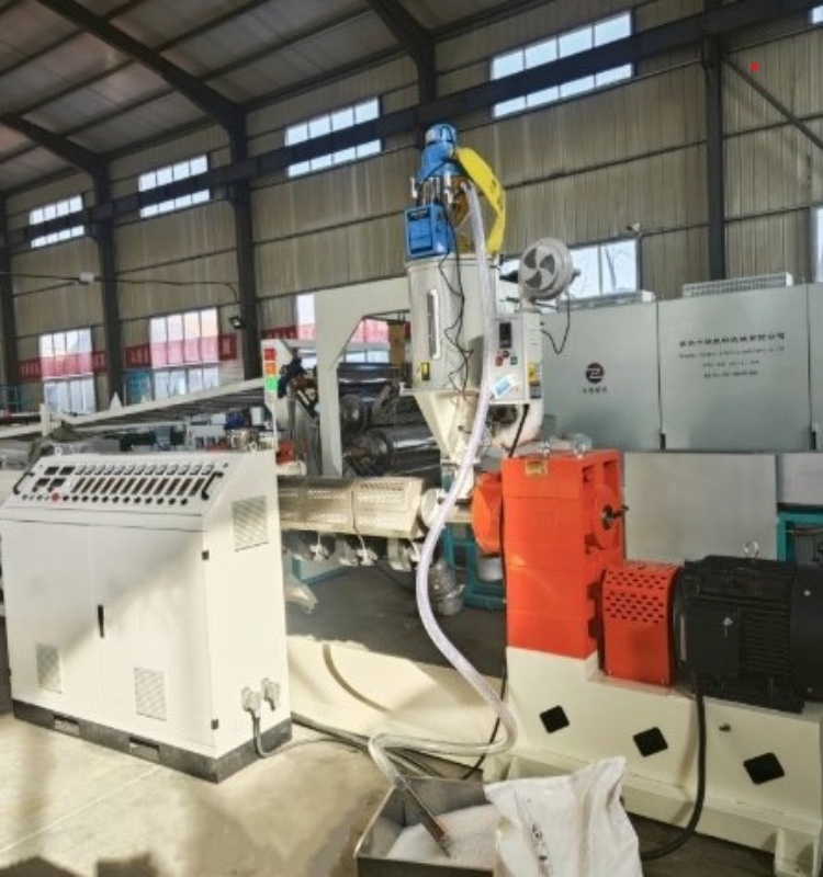
Raw Material Handling and Gravimetric Dosing
The foundation of any reliable PE pipe extrusion line begins long before the polymer enters the extruder barrel. Raw material handling dictates the baseline quality of the final product. While polyethylene itself is not highly hygroscopic, the carbon black masterbatch used for UV resistance in pressure pipes absorbs moisture rapidly. Automated drying and blending systems remove ambient moisture from the resin mix. Even trace amounts of moisture cause surface defects, internal voids, and reduced mechanical strength in the finished pipe. You must achieve a homogenous mix of virgin resin—specifically pressure grades like PE80 and PE100—alongside masterbatch and regrind material.
Gravimetric dosing systems replace older volumetric feeders by operating on a loss-in-weight principle. These systems continuously measure the exact mass of material entering the extruder. By synchronizing the feed rate with the extruder screw speed and haul-off speed, gravimetric dosers control the exact weight per meter of the extruded pipe. This precision reduces material giveaway, prevents wall thickness fluctuations, and ensures the structural integrity required for high-pressure water and gas distribution networks. Operators rely on these systems to maintain tight tolerances without constant manual adjustments.
The Extruder Unit
The single-screw extruder functions as the heart of the system. It melts, mixes, and pumps the polymer. High-density polyethylene possesses a high melt viscosity, requiring specific screw geometries to process efficiently without inducing thermal degradation. Modern extruders utilize barrier screws designed to separate the solid polymer bed from the melt pool. This separation increases melting efficiency and ensures a uniform melt temperature across the entire output.
Evaluation criteria for extruder screws heavily feature the Length-to-Diameter (L/D) ratio. For processing PE and HDPE, L/D ratios typically range between 33:1 and 38:1. A longer barrel provides more residence time for the polymer, allowing for gentler heating and thorough mixing. Grooved feed bushes are integrated into the feed zone. These grooves increase the friction between the solid pellets and the barrel wall, dramatically improving the conveying capacity and enabling high-throughput melting even at lower screw RPMs. If the feed zone lacks proper water cooling, the pellets will bridge and block the intake.
Die Head and Tooling
Once the polymer exits the extruder, it enters the die head. The primary function of the die head is to transform the solid mass of molten polymer into a hollow tubular profile. For PE pipe manufacturing, spiral mandrel die heads are the industry standard. Unlike older spider dies, spiral mandrel designs distribute the melt through a series of helical channels that gradually merge. This fluid dynamic action eliminates weld lines—areas of mechanical weakness where polymer flow fronts meet—and ensures uniform melt distribution around the entire circumference of the pipe.
Tooling flexibility represents another critical evaluation point. Manufacturers frequently need to switch pipe diameters to fulfill different orders. Advanced die heads feature interchangeable pins and bushes. Quick-change tooling systems allow operators to adjust the outer diameter and wall thickness efficiently, preventing prolonged downtime and reducing the volume of scrap generated during product changeovers. Proper centering of the die pin is mandatory; even a millimeter of offset will cause severe wall thickness variations.
Standard Temperature Profile for HDPE Extrusion
Extruder Zone
Target Temperature Range (°C)
Function
Feed Zone (Zone 1)
170 - 180
Initial pellet warming and conveying
Compression (Zone 2-3)
185 - 195
Primary melting and shear heating
Metering (Zone 4-5)
195 - 205
Homogenization and pressure building
Adapter / Screen Pack
205 - 210
Filtration and flow transition
Die Head Zones
200 - 215
Final shaping and surface finish
The Step-by-Step PE Pipe Production Line Process
Stage 1: Melting and Homogenization
The standard PE pipe production line initiates the transformation process inside the extruder barrel. As the screw rotates, it generates mechanical shear. The friction between the polymer pellets, the screw flights, and the barrel wall creates the majority of the heat required for melting. External heater bands provide supplementary heat and maintain specific temperature profiles across different barrel zones. Precise Proportional-Integral-Derivative (PID) temperature control is critical here. If the temperature drops too low, unmelted particles will cause weak spots. If the temperature spikes, the polymer chains degrade, compromising the pipe's pressure rating.
Stage 2: Extrusion and Shaping
The homogenized polymer melt pushes through the screen pack and breaker plate. These components filter out impurities, un-melted gels, and foreign contaminants while converting the rotational flow of the melt into a linear flow. The melt then enters the spiral mandrel die head. The pressure inside the die forces the polymer over the mandrel (forming the inside diameter) and through the sizing ring (forming the outside diameter). At this stage, the polymer is entirely molten and highly susceptible to gravity and ambient temperature fluctuations. The drawdown ratio must be calculated correctly to ensure the melt stretches slightly as it exits the die without tearing.
Stage 3: Vacuum Calibration and Sizing
Immediately after exiting the die, the molten pipe enters the vacuum sizing tank. This stage freezes the outer diameter to exact specifications. The pipe passes through a sizing sleeve (calibrator) typically made of bronze or stainless steel. A vacuum is drawn inside the tank, pulling the soft polymer outward against the inner wall of the sizing sleeve. Simultaneously, cooling water is applied to the pipe surface through a water ring. The balance between vacuum pressure and cooling rate is delicate. Incorrect vacuum levels lead to ovality, while uneven cooling causes internal stress. Operators must monitor the vacuum gauge constantly; a drop in pressure usually indicates a seal failure or a blockage in the water ring.
Stage 4: Cooling and Solidification
Following calibration, the pipe travels through a series of multi-stage spray cooling tanks. High-density polyethylene acts as a thermal insulator, meaning it retains heat efficiently. Cooling must be applied gradually to prevent the outer surface from shrinking faster than the inner core, which induces residual stress and potential cracking. The calculation of cooling tank length depends entirely on the pipe's wall thickness and the line speed. Thick-walled pipes require exceptionally long cooling zones, sometimes exceeding 30 meters, to ensure the core reaches a stable temperature before the pulling phase. Spray nozzles must be inspected daily to ensure full 360-degree coverage; a clogged nozzle will cause a hot streak on the pipe, leading to warping.
Stage 5: Haul-Off (Pulling) Mechanics
The haul-off unit pulls the solidified pipe through the cooling tanks at a constant velocity. Multi-caterpillar haul-off machines use cleated rubber belts to grip the pipe. The number of caterpillars ranges from two for small flexible pipes to twelve or more for large-diameter rigid pipes. Synchronized pulling speed is paramount. If the haul-off pulls too fast, the pipe wall thins out and stretches. If it pulls too slowly, the pipe bunches up at the die head. Advanced servo drives ensure the pulling speed remains locked in synchronization with the extruder screw speed. Track pressure must be adjusted carefully to avoid crushing the pipe while maintaining enough grip to prevent slipping.
Stage 6: Inline Printing and Traceability Marking
Regulatory standards dictate that pressure pipes must carry permanent identification. Inline printing systems, utilizing either continuous inkjet or laser marking technology, apply this data directly onto the pipe surface as it moves. The marking typically includes the manufacturer's name, pipe dimensions, standard dimension ratio (SDR), pressure rating, resin type (e.g., PE100), and the exact date and time of manufacture. Laser marking is increasingly preferred for its permanence and lack of consumable ink. The printer must be synchronized with the haul-off encoder to ensure the text remains legible regardless of line speed fluctuations.
Stage 7: Cutting and Facing
Once marked, the continuous pipe must be severed into manageable lengths. The cutting mechanism depends on the pipe format. Large-diameter rigid pipes require planetary cutters, where a circular saw blade revolves around the pipe circumference. Small-diameter flexible pipes are often cut by simple guillotine shears or fed directly into automated coilers. Swarfless cutting mechanisms are highly recommended to prevent plastic dust from contaminating the facility. Clean, square cuts (facing) are essential because uneven pipe ends severely complicate downstream butt-fusion welding during field installation. A chamfering tool is often integrated into the planetary saw to bevel the pipe edge automatically.
Stage 8: Discharging, Coiling, and Post-Production QA
The final stage involves handling the finished product. Rigid pipes are pushed onto automated tipping tables that gently roll the cut lengths into stacking racks. Flexible pipes are wound onto tension-controlled coilers, ensuring the coils are tight but not stretched. Production does not end at the machine; the process transitions to offline batch testing. Samples are subjected to hydrostatic pressure testing, impact resistance trials, and melt flow index verification to guarantee the batch meets final product certification before shipping.
Technical Evaluation Dimensions for an HDPE Pipe Production Line
Evaluating an HDPE pipe production line requires looking beyond basic output numbers and examining the technical architecture that drives efficiency and consistency. You must scrutinize the control systems and power consumption metrics.
Automation and PLC Integration
Modern extrusion lines rely heavily on centralized automation. Programmable Logic Controllers (PLCs) manage the complex interplay between temperatures, speeds, and pressures. Centralized control systems enable recipe management, allowing operators to load predefined parameters for specific pipe sizes instantly. Alarm logging provides diagnostic data for troubleshooting, while synchronized drive control ensures that if the extruder speed fluctuates, the dosing and haul-off speeds adjust automatically to maintain product dimensions. A robust Human-Machine Interface (HMI) allows operators to monitor melt pressure, motor load, and zone temperatures from a single screen.
Throughput Capacity vs. Energy Consumption
Output capacity (measured in kg/hr) must be evaluated against power usage (measured in kW/hr). High throughput is only profitable if the energy overhead remains manageable. Permanent Magnet Synchronous Motors (PMSM) have largely replaced standard AC motors in high-end extruders. PMSMs deliver higher torque at lower speeds and operate with significantly greater energy efficiency, reducing the electrical load of the main drive by up to 20%. You must calculate the Specific Energy Consumption (SEC) of the line to understand its true operational efficiency.
Extruder Motor Technology Comparison
Motor Type
Energy Efficiency
Maintenance Requirement
Torque Delivery at Low RPM
Standard AC Asynchronous
Moderate
Low
Moderate
DC Motor
Low
High (Brush replacement)
High
Permanent Magnet Synchronous (PMSM)
High
Very Low
Very High
Inline QA/QC Capabilities
Relying solely on offline batch testing results in excessive scrap if a defect goes unnoticed for hours. Inline Quality Assurance (QA) integrates ultrasonic wall thickness scanners directly after the vacuum calibration tank. These scanners measure the pipe's concentricity and wall thickness in real-time. When paired with closed-loop feedback systems, the PLC automatically adjusts the haul-off speed or the extruder RPM based on the ultrasonic data, maintaining strict dimensional accuracy without manual intervention. If the wall thickness drops below the SDR tolerance, the system triggers an immediate alarm.
Implementation Risks and Mitigation Strategies
Managing Material Waste during Startup
The startup phase of an extrusion line represents the highest risk for scrap generation. Bringing a cold machine up to operating temperature and stabilizing the melt flow takes time. During this period, the extruded pipe will not meet dimensional tolerances. Mitigation strategies include utilizing automated bleed valves on the die head to purge degraded material quickly. Implementing precise thermal profiling and automated startup sequences in the PLC reduces the time it takes to achieve a stable melt, thereby minimizing wasted resin. You must enforce a strict heat-soak period before starting the main drive to prevent shearing the screw shaft.
Standard Startup Sequence
Verify all water cooling lines to the feed throat and gear box are open and flowing.
Activate barrel and die heater bands to target temperatures.
Initiate a 45-minute heat-soak period once target temperatures are reached.
Start the main extruder drive at a low RPM (e.g., 5-10 RPM) to purge residual material.
Gradually increase screw speed while simultaneously engaging the haul-off unit.
Engage the vacuum pump and adjust sizing sleeve water flow once the pipe enters the calibration tank.
Facility Footprint and Utility Demands
Industrial extrusion requires significant physical space and robust utilities. Long cooling lines are mandatory for large-diameter pipes, often requiring factory floors exceeding 50 meters in length. Buyers must accurately map their facility footprint before purchasing equipment. Additionally, the process consumes massive volumes of cooling water. Implementing closed-loop water chilling systems is essential to mitigate excessive industrial water consumption, recycling the cooling water and maintaining it at the precise temperatures required for optimal polymer crystallization. Ensure your compressed air system can handle the CFM requirements of the planetary cutter and pneumatic tipping tables.
Operator Training and Maintenance Protocols
Advanced extrusion lines are complex thermodynamic systems that require skilled technicians. A common implementation risk is handing sophisticated machinery to an undertrained workforce. Vendor-supplied training is critical. Operators must understand the intricacies of die assembly, proper screw cleaning procedures, and the physics of polymer behavior. Establishing strict preventative maintenance schedules prevents unexpected mechanical failures and prolongs the lifespan of the equipment.
Routine Maintenance Checklist
Inspect and clean the vacuum pump filters daily to maintain consistent calibration pressure.
Check the gearbox oil level and inspect for metal shavings monthly.
Verify the calibration of the gravimetric dosing load cells every quarter.
Clean the spray nozzles in the cooling tanks weekly to prevent mineral buildup.
Inspect the haul-off caterpillar pads for uneven wear and replace as necessary.
Extrusion Defect Troubleshooting
Observed Defect
Potential Cause
Corrective Action
Melt Fracture (Sharkskin)
Melt temperature too low or extrusion speed too high
Increase die temperature or reduce screw RPM
Uneven Wall Thickness
Die pin is off-center or uneven cooling in calibration tank
Adjust die centering bolts; check water ring flow
Pipe Ovality
Insufficient vacuum pressure or pipe is too hot entering haul-off
Clean vacuum filters; increase cooling water flow
Internal Voids / Bubbles
Moisture in raw material or excessive barrel temperature
Check material dryer operation; lower zone 3-4 temps
Die Lines (Scratches)
Contamination in the die or damaged sizing sleeve
Purge extruder; inspect and polish sizing sleeve
Conclusion
Audit your current production bottlenecks by analyzing scrap rates and downtime logs from the past six months.
Define your exact required diameter ranges, SDR ratings, and output capacities based on upcoming contract demands.
Evaluate your facility's utility infrastructure, specifically focusing on available floor space, electrical capacity, and chilled water supply.
Request a detailed technical consultation and customized line layout from a qualified equipment manufacturer.
FAQ
Q: What is the standard L/D ratio for a modern HDPE pipe production line?
A: Typically 33:1 to 38:1, optimized for high-density polyethylene to ensure proper melting without thermal degradation.
Q: How does a versatile PE HDPE PPR pipe production line differ from a dedicated line?
A: Versatile lines utilize specialized screw geometries and interchangeable die heads to handle the different melt flow indices and processing temperatures of PE, HDPE, and PPR materials.
Q: Why is vacuum calibration necessary in PE pipe extrusion?
A: It forces the molten polymer against the sizing sleeve while cooling begins, ensuring the pipe achieves and maintains its exact outer diameter and roundness.
Q: How much cooling water is required for a standard PE pipe extrusion line?
A: Volumes vary heavily by pipe diameter and line speed, but modern systems use closed-loop chillers to recycle up to 95% of the water, minimizing utility demands.
Q: What causes inconsistent wall thickness during PE pipe manufacturing?
A: Common culprits include uneven melt temperatures, uncalibrated gravimetric dosing, fluctuating haul-off speeds, or improper die head centering.
Q: Can an existing PE pipe production line be upgraded for higher throughput?
A: Yes, upgrades often include installing grooved feed bushes, retrofitting permanent magnet synchronous motors, or adding closed-loop gravimetric dosing systems to increase efficiency.
Qingdao Zhongrui Plastic Machinery Co., Ltd. is located in Jiaozhou City, Qingdao City, Shandong Province. It is 30 kilometers away from Qingdao Port and only 20 kilometers away from the airport.



 +86-18561886575 (Mr.Wu)
 +8618561886575
 238 Yangzhou West Road, Jiaozhou City, Qingdao City, Shandong Province